ОСНОВНЫЕ НАПРАВЛЕНИЯ РАЗВИТИЯ ТЕХНОЛОГИЙ КОСМИЧЕСКОГО ПРИБОРОСТРОЕНИЯ
Сумский государственный университет
аспирант
Аннотация
Данная статья посвящена обзору основных направлений усовершенствования технологий приборостроения для космических аппаратов.
Ключевые слова: космический аппарат, параметры, приборостроение, технологии
MAIN DIRECTIONS OF SPACE DEVICE TECHNOLOGIES DEVELOPMENT
Sumy State University
PhD-Student
Abstract
This article provides an overview of the main areas of instrumentation technologies improvement for spacecraft.
Keywords: instrumentation, parameters, spacecraft, technology
Библиографическая ссылка на статью:
Омельяненко В.А. Основные направления развития технологий космического приборостроения // Современная техника и технологии. 2013. № 10 [Электронный ресурс]. URL: https://technology.snauka.ru/2013/10/2498 (дата обращения: 31.07.2026).
Instrument engineering is an important factor in the development of the space industry, involvement in work which requires innovation, as implementing the scientific and technological potential.
Among the promising areas of space instrument we should highlight:
- expansion of operating spectral bands;
- increasing the number of spectral channels and increase the metric properties of information technology equipment in the pursuit of international requirements;
- establishment of a number of innovative instrumentation for space information devices based on the newly developed methods;
- increasing the capacity of radio transmission destination information (including the development of new radio frequency bands), while maintaining the task of using existing ground-based receiving facilities and the application of international frequencies and data transmission formats;
- improving co-ordinate the timing of the target information, automation, land of primary and secondary treatment standard;
- rational distribution of information appliances for individual spacecraft, ensuring compatibility and complementarity of both types of information obtained;
- electromagnetic compatibility and geometrical instruments on board satellites;
- optimum utilization of radio resources and power supply spacecraft, etc.;
- optimization of building a ballistic orbital group to raise funds periodic review of global observations, a limited number of space vehicles, as well as a balanced mix of spans , the spatial resolution and radiometric properties of various information technology equipment on one side;
- increasing the lifetime of information technology equipment and space vehicles in general to the optimum values.
The solution of these problems causes the internationalization of innovation processes in the instrument. Today, the largest organization concerned with the construction of telescopes and observatories , as well as their management is the European Southern Observatory, ESO (European Organization for Astronomical Research in the Southern Hemisphere), founded in 1962, currently it includes 15 countries – Austria, Belgium, Brazil, United Kingdom, Germany, Denmark, Spain, Italy, Netherlands, Portugal, Finland, France, Czech Republic, Sweden and Switzerland. ESO budget was 163.2 million euros in 2010, while the number of workers and employees – about 730 people [1].
A wide range of observation devices in the range from 300 nm to 25 microns provides a large number of tasks, ranging from studies of objects in our solar system and ending with the distant galaxies and quasars. Support from the ESO makes the whole process as easy and affordable for astronomers, thus contributing to scientific progress.
The most important destinations in the area include the development of space instrumentation equipment for meteorological satellites and spacecraft remote sensing of the Earth and Mars, including blocks of image registration of the visible and infrared bands, digital control systems of one-and two-coordinate precision of the optical scanner.
In this context, the main processes for ordering maintenance of intellectual property rights on the major stages of the life cycle and automate key procedures of distributed control of intangible assets identified following relatively independent subsystems [5, P. 130].
1) subsystem methods, models, techniques and processes of research, development and operation of on-board control;
2) subsystem software, databases, knowledge base and the know-how on-board control / regulation;
3) subsystem of inventions, utility models, industrial designs, trademarks and logos;
4) subsystem of the methods and models of formation and maintenance of the subjects and objects of IP;
5) subsystem of the methods and models of IP valuation and intangible assets;
6) subsystem methods and models for strategic planning and forecasting of space instrumentation.
To launch vehicles and spacecraft to satisfy the requirements of reliability, durability and efficiency, in the world they are carefully and thoroughly tested under conditions most appropriate available at the start and during the orbital flight. Professionals, in particular, interested in the answers to the question of how to outsource “soft” instruments vibration and overloads, what is the degree of tightness of devices, the system works as a single supply, the behavior of different materials under high vacuum at extreme temperatures and more.
An important place in ground tests of spacecraft is the study of the thermal regime. Hard weight and power constraints force designers to create a thermal control system without significant reserves of refrigerant or heat. In these circumstances, even a slight error in the calculation of heat may result in that the heat treatment of the spacecraft would not be maintained within the specified limits and cause failure of onboard equipment.
As it shown in Fig. 1, particularly thermal conditions (even within allowable range) strongly influence the reliability of the spacecraft. The smallest number of failures observed at normal room temperature. With its decreasing the number of failures increases to be significant at lower temperatures and more particularly at elevated.
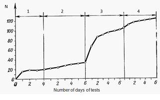
Fig. 1. The dependence of the number of failures of equipment 11 spacecraft on the ambient temperature [3]
1 – room temperature, 2 – phase transition from the maximum to the minimum allowable temperature devices, 3 – minimum allowable temperature devices, 4 – the maximum allowable temperature devices.
Recent advances in electronics, particularly in the production technology of integrated circuits, designed to meet the requirements for establishing a new data acquisition and processing unit. Much more difficult is the case with sensors of physical quantities: an attempt to miniaturization while increasing the level of metrological parameters needs to attract and achievements in materials science, manufacturing technology and, of course, requires a serious theoretical justification.
Specialists of the Institute of Precision Mechanics and Computer Engineering named after S.A. Lebedev RAS have developed a system management tool HEND, working aboard interplanetary spacecraft Mars Odyssey. The device HEND (High Energy Neutron Detector) is a detector neurons and is designed to study Mars from orbit elemental composition of the surface of this planet and the search for areas with water ice at a depth of 1-2 meters. HEND is part of a complex experiment Gamma-Ray Spectrometer for Mars gamma spectroscopy and records bursts of cosmic gamma radiation and also gamma rays, and neutrons from powerful solar flares. The device has been developed at the Institute for Space Studies commissioned by the Russian Aviation and Space Agency and installed aboard a U.S. spacecraft on the basis of an intergovernmental agreement between Russia and the United States.
The detector HEND gathered a huge amount of traffic data of neutrons at distances from 250 to 20,000 km from the surface of Mars (measured during 70 revolutions around the planet tapered). These data provide a 3-D model of the neutron cloud around the planet.
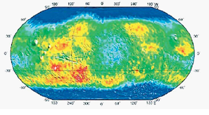 Fig. 2 – Distribution ice surface layer Mars according to the detector neurons HEND
The main difficulty in creating DAN was associated with joint castings and test our device in the United States – we had to adapt to the new conditions of work to the standards and requirements of NASA, different from our requirements and standards.
Among the many factors affecting the operation of the electronic equipment during its operation, particular importance is the impact of field space ionizing radiation – electrons, protons and ions. The widespread use of semiconductor microelectronics as the element base of space electronic systems has made the task of assessing the actual and forecast levels of component failures and units for radiation effects of outer space. Traditionally, software and forecasting of radiation resistance of integrated circuits is based on the requirements of the relevant regulatory and technical documents.
Thus, for these goals abroad U.S. standards MIL-STD-883 and the European Space Agency ESA / SCC Basic Specification are used.
Consider, for example, an estimate of the failure rate of digital logic MOS integrated circuits average level of integration. In general, for all classes of IC failure rate in accordance with MIL-HDB-217 is calculated as follows [2]:
λ = λGπQ,
λG = (C1πTπV + C2πE)πL × 10–6 h–1,
where λG – failure rate, excluding the quality factor πQ;
C1 – coefficient complexity of integrated circuits; C1 = 0,04 for the number of gates from 1000 to 3000;
πT – temperature coefficient; πT = 1,1 for the transition temperature, equal to 50°С, for non-hermetic housings schemes;
πV – voltage coefficient; πV = 1 at UCC < 12 V and all other technologies;
C2 –coefficient of enclosures; for non-hermetic enclosures
C2 = 2×10⁻⁴(NP) 1,23,
where NP – number external leads;
C2 = 0,007 for 18- leads IC chips;
πЕ – coefficient of influence of environmental conditions; πЕ = 0,45 for the conditions of the spacecraft;
πL – coefficient of scrutiny; πL = 1 for serial ECB with the established technology.
Given the values of the above ratios: λG = 0,0528 × 10⁻⁶ h–1.
The quality factor for the industrial performance IC chips is 10.0 (for comparison, πQ IC space applications, in which a Class S, is 0.25.)
Table 1. Quality levels of foreign IC chips [2]
| Level of quality (πQ) |
European IC chips |
American IC chips |
| Space, πQ ≅ 0,25 |
Level В (acceptance test LAT1, LAT2, LAT3) |
JANS QPL38510 |
|
CLASS V QML38535 |
||
| Military, πQ ≅ 1,0 |
Level С (acceptance test LAT1, LAT2, LAT3) |
JANS QPL38510 |
|
CLASS Q QML38535 |
||
| Average military, πQ ≅ 2,0 |
Experimental level (level C without the acceptance tests LAT1, |
SMD (38536 Class M). The production line in quality level, tested in accordance with paragraph 1.2.1 MIL-STD-883 |
| Low military, πQ ≅ 5,0 |
Reduced the amount of testing compared with classes B and C |
Reduced the amount of testing compared with the classes S and B MIL-STD-883 |
| Industry, πQ ≅ 10,0 |
integrated microcircuits leaks with additional thermal testing: industrial temperature range -25 to +100°С |
|
| Commercial, πQ ≅ 20,0 |
integrated microcircuits leaks with additional thermal testing: commercial temperature range от 0 до 80°С |
|
Recently in our country and abroad, a trend towards the use of electronic equipment in space systems elements of the industrial class instead of an expensive and difficult foreign electronic component base class space after extensive program of the reject and diagnostic tests based on the analysis of non-destructive testing methods, as well as structural control and physical analysis of representative samples of IC chips from each party.
In the short term (3-5 years) can be expected the development of new materials and methods for protection of parts and components aircraft and space technology against wear and corrosion at high temperatures, quantum computers obtaining nanomaterials (powders, ceramics, composites) with new properties, industrial, aerospace alloys a new destination of titanium, zirconium, hafnium, etc.
References
- Боли П.Э. Европейская Южная Обсерватория и телескопы VLT на Паранале / П.Э. Боли // Физика Космоса: Тр. 41-й Международ. студ. науч. конф., Екатеринбург, 30 янв. – 3 февр. 2012 г. – Екатеринбург: Изд-во Урал. ун-та, 2012. С. 7-18.
- Данилин Н. Проектирование и разработка космических бортовых приборов, ориентированных на современную зарубежную электронную компонентную базу / Н. Данилин, С. Белослудцев // Современная электроника. 2008. № 4. С. 54-59.
- Салахутдинов Г.М. Космос начинается на земле [Электронный ресурс]. – Режим доступа: http://www.astronaut.ru/bookcase/books/salah03/text/08.htm
- Салахутдинов Г.М. Тепловая защита в космической технике. Мл Знание, 1982. 64 с.
- Сыров А.С. Методы и модели распределенного управления основными процессами проектирования многопроцессорных систем космических аппаратов / А.С. Сыров, Б.Н. Попов, С.П. Ботуз // Всероссийская суперкомпьютерная конференция "Научный сервис в сети Интернет: масштабируемость, параллельность, эффективность". 2009. С. 130-133.
- Чуркин А.Л. Гидрометеорологический и океанографический космический комплекс четвертого поколения «Метеор МП» // Геоматика. 2011. №2(11). C. 29-33.
Все статьи автора «Омельяненко Виталий Анатольевич»
© Если вы обнаружили нарушение авторских или смежных прав, пожалуйста, незамедлительно сообщите нам об этом по электронной почте.